Analog and digital microphone output signals clearly have different considerations in their design. This article will discuss the differences between the analog and digital MEMS microphones into the system design and the factors to consider.
MEMS microphone internal details
The MEMS microphone output is not directly from the MEMS transducing unit. The transducer is essentially a variable capacitor and has a particularly high megaohm output impedance.
In the microphone package, the transducer signal is first sent to the preamplifier, and the primary function of this amplifier is impedance conversion, which reduces the output impedance to a more appropriate value when the microphone is connected to the audio signal chain. The output circuit of the microphone is also implemented in this preamplifier circuit.
For an analog MEMS microphone, the circuit shown in Figure 1 is basically an amplifier with a special output impedance. In digital MEMS microphones, this amplifier is integrated with an analog-to-digital converter (ADC) to provide a digital output in pulse density modulation (PDM) or I2S format.
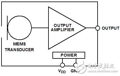
Figure 1: Block diagram of a typical analog MEMS microphone
Figure 2 is a functional block diagram of a PDM output MEMS microphone, and Figure 3 is a typical I2S output digital microphone. The I2S microphone contains all the digital circuitry in the PDM microphone, as well as a decimation filter and serial port.
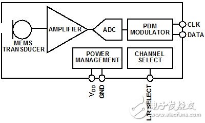
Figure 2: Typical PDMMEMS microphone block diagram
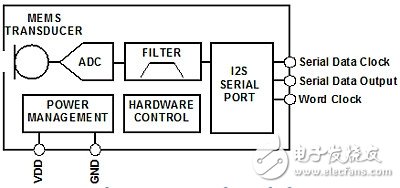
Figure 3: Typical I2S MEMS microphone block diagram
MEMS microphone packages are unique in semiconductor devices because there is a hole in the package for the acoustic energy to reach the transducer unit. Inside this package, the MEMS microphone transducer is tied to an analog or digital ASIC and mounted on a common stack. A cover is then attached over the stack to seal the transducer and ASIC. This stack is typically a small piece of PCB that is used to connect the signals from the IC to the pins on the outside of the microphone package.
Figures 4 and 5 show the internal details of the analog and digital MEMS microphones, respectively. In these pictures, you can see the transducer on the left and the ASIC on the right (under the epoxy), both mounted on the stack. The digital microphone has an additional tie line that connects the electrical signal from the ASIC to the stack.
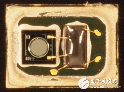
Figure 4: Transducers and ASICs in analog MEMS microphones
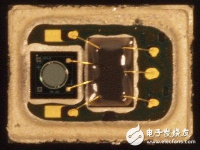
Figure 5: Transducers and ASICs in digital MEMS microphones
With our expertise in domain, we offer comprehensive range of Monocrystalline Solar Panels. Our products are used amongst the customers across the country for their effectiveness. We offer products to our patrons as per their needs and are easy to install. These products work using solar energy and have high performance.which are made using high quality raw material and advanced technologies. These Polycrystalline Solar Panels are checked for quality on various parameters. These products are highly resistant towards the winds and the hailstones and serves for a longer period of time.
Mono 150W Solar Panel,150W Mono Pv Solar Panel,Mono Solar Panel 150W,150 Watt Mono Solar Panel
Yangzhou Bright Solar Solutions Co., Ltd. , https://www.solarlights.pl