1 Introduction
In 2013, Cypress introduced the PSoC4, the latest product in the Programmable System on Chip family of Programmable System-on-Chip (PSoC), which uses the ARM Cortex-M0 as the processing core. PSoC4 fully inherits the highly programmable flexibility of the PSoC chip family itself, and combines the Cortex-M0 cost-effective processor core architecture, making the PSoC4 series a highly scalable processor platform, cost-effective, The advantages in terms of consumption and so on are significant. It is worth mentioning that PSoC4 provides complete and unique on-chip resources for motor control, so engineers will be more intuitive and fast when developing motor control systems on PSoC4.
The PSoC4 product line is currently available in two entry-level product families, the CY8C4100 and CY8C4200. This article takes CY8C4200 as an example to introduce how to develop a three-phase brushless DC motor control system with sensors on PSoC4.
2. PSoC4 architecture and on-chip profile related to motor control
PSoC 4 is a family of programmable embedded system controllers based on the ARM Cortex-M0 CPU (processor), providing a powerful programmable platform for embedded applications. It combines programmable analog resources, programmable interconnects, user-programmable digital logic, a common fixed-function design, and a high-performance ARM Cortex-M0 CPU subsystem. Figure 1 below shows the system block diagram of PSoC4.
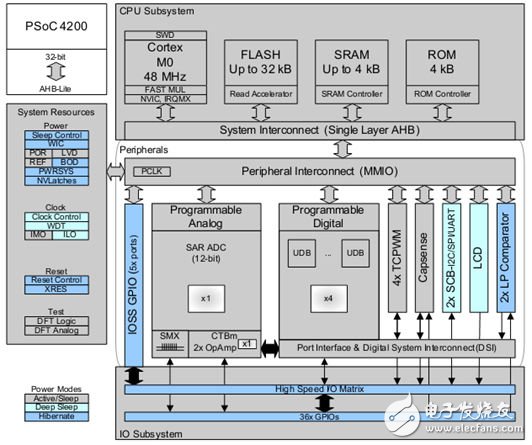
Figure 1: System Block Diagram of PSoC4
PSoC4 is consistent with the previous generation of the PSoC family in the development environment. It is still PSoC Creator, continuing the development method of abstracting on-chip resources into modular components. The control system architecture is clear and specific, simple and fast. Users can pay more attention to the functional development of the product, and pay less attention to the hardware structure details of the chip.
3. Control principle of sensorless brushless DC motor and analysis of main commercial control cases
1 Brushless DC motor control principle
Brushless Direct Current (BLDC) motors are gaining popularity in automotive, appliance, industrial automation, aerospace and medical equipment applications and will continue to replace brushed motors. Thanks to electronic commutation, BLDC motors have a longer life and less operating noise. In addition, with the further improvement of soft magnetic material technology and the continuous decline of price, BLDC motors will use more high-performance NdFeB rare earth materials to make permanent magnet rotors. The higher magnetic energy product and stable characteristics make BLDC motors. Better mechanical properties and dynamic response, higher efficiency and speed range. Therefore, BLDC motors will be further promoted in medium and high-end applications where environmental and performance requirements are more demanding.
In principle, the stator and rotor magnetic fields of the BLDC motor have the same frequency and speed, so they are one type of synchronous motor. The stator winding can be wound into single-phase, two-phase and three-phase, and the three-phase BLDC motor is most widely used due to its large output power, small torque ripple and high efficiency. The research object of this paper will also be placed on the control system of the three-phase BLDC motor.
The three-phase BLDC motor uses a two-phase sequential energization mode to generate a rotating magnetic field. The conduction of the stator windings of each phase is uniquely determined by the rotor position to ensure that the rotor can always output the maximum torque. Since the mechanical brush of the automatic commutation is eliminated, the spatial position of the rotor needs to be detected in real time, and the Hall effect sensor is widely used because of its high cost performance and ease of installation. For a two-phase, three-phase BLDC motor, each electrical cycle is divided into six different energization intervals, so three Hall sensors are required for partitioning. Figure 2 is a plot of the typical Hall sensor output signal versus the corresponding conduction phase. Each change in the Hall sensor requires a real-time change in the conduction phase, and the motor operates in a sequential sequence of established logic.
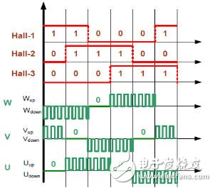
Figure 2: Hall sensor signal and phase winding conduction diagram
2 Analysis of main commercial control cases of brushless DC motors
At present, major mainstream semiconductor manufacturers have introduced their own sensor BLDC motor control solutions, the technology is similar, and relatively mature. In summary, the output of the three-way Hall sensor is connected to the input pin of the MCU. Each level change will trigger an interrupt. In the interrupt service routine, the corresponding turn-on is changed according to the logic of Figure 2. Phase, to achieve the purpose of commutation.
Figure 3 is a schematic diagram of the mainstream commercial solution on the market. Through simple analysis, we can find that the MCU is commutating through the interrupt service program. In the monitoring of the motor current, the current signal is sent to the ADC by the external sampling and operational amplifier circuit. The software program compares and determines whether the current is over-current and turns off the PWM output to protect the motor and circuitry.
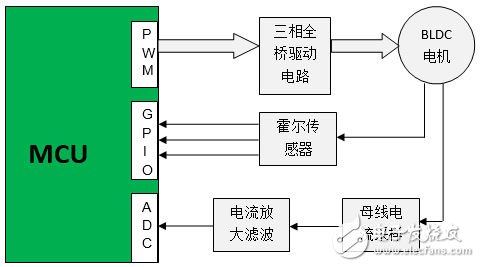
Figure 3: Schematic diagram of mainstream commercial solutions for BLDC motors
In general, the control of BLDC motors is simpler than that of permanent magnet synchronous motors and stepper motors. The solution architecture of semiconductor manufacturers is generally similar, and the technology is becoming more homogeneous. Through further analysis, it can be found that the commutation of the motor and the monitoring of the current are all done in software, but the amplification and processing of the current requires an external operational amplifier circuit, which is slow, costly and unreliable. In addition, the hardware detection of Hall sensor failure lacks real-time and effective means, affecting the safe operation of the motor.
4. PSoC4-based brushless DC motor control architecture and advantages analysis
The ARM Cortex-M0 high-performance processing core used in PSoC4 not only can quickly complete the closed-loop speed adjustment of the motor and other corresponding control operations, but its internally integrated programmable UDB can cure the commutation logic shown in Figure 2 in the form of CPLD. In the chip, faster and more reliable hardware commutation is achieved without software intervention. In addition, UDB can directly detect the failure state of the Hall signal and immediately turn off the PWM output to quickly protect the motor.
The PSoC4 integrates an op amp (Opamp) that supports the comparator mode and a programmable IDAC current source, so the motor current monitoring can be fully integrated into the PSoC4 on-chip without any external active components. The motor current enters the on-chip Opamp after passing through the sampling resistor, and is amplified as the positive input of the on-chip comparator. The negative input of the comparator is the overcurrent threshold reference generated by the on-chip IDAC current source. The transition of the comparator output will directly turn off the PWM output and protect the motor.
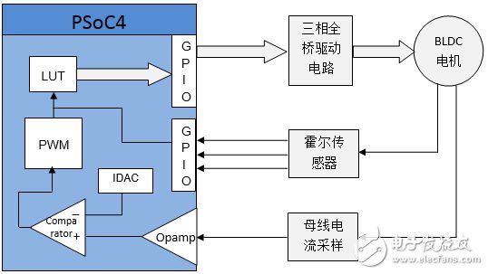
Figure 4: PSoC4-based brushless DC motor control block diagram
Compared with the PSoC4-based control scheme and the current mainstream commercial solutions on the market, it is not difficult to find that PSoC4 can integrate the on-chip hardware to complete the sequential commutation of the brushless DC motor by integrating the rich on-chip analog and digital resources. Current monitoring is faster and more reliable than software implementation and saves considerable cost of off-chip active devices. In addition, the on-chip UDB can directly detect the failure state of the Hall sensor and quickly protect the motor, which is an important function that other manufacturers do not have.
5. Design of Brushless DC Motor Control System Based on PSoC4
1 Control schematic design
According to the control block diagram of Figure 4, we designed the BLDC motor control schematic shown in Figure 5 in the PSoC Creator environment.
After the Hall signal is directly input to the UDB commutation logic table LUT_Cmut via the I/O pin, the three-phase full-bridge circuit is directly driven to complete the hardware commutation of the motor. At the same time, the Hall signal is also synchronously input to another UDB logic table LUT_Spd, which realizes the failure state detection of the Hall sensor and completes the speed detection of the motor.
After the motor current is input to the on-chip op amp Opamp_1 through the sampling circuit, it is input to the on-chip comparator after op amp and filtering, and compared with the overcurrent threshold reference generated by the on-chip IDAC. After the inversion, the PWM output is directly turned off. The phase logic table LUT_Cmut is used to de-energize the motor.
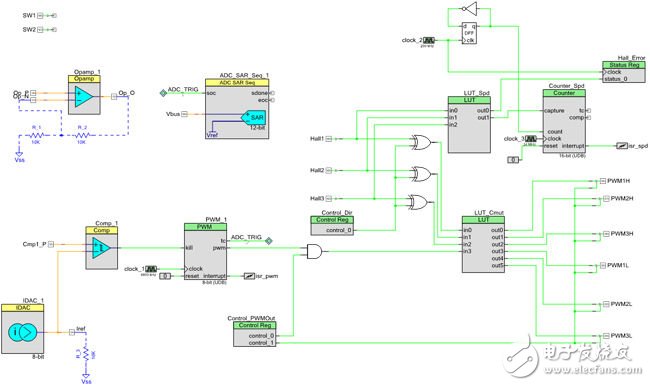
Figure 5: Stepper motor control schematic
2 control system software design
Due to the use of PSoC4 on-chip hardware for commutation, Hall failure detection and overcurrent detection protection, the software design of the system is relatively simple, just read the user command and complete the closed-loop speed adjustment. Figure 6 is a block diagram of the main program flow of the control system.
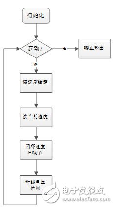
Figure 6: Main program flow chart
The control main program first initializes and configures the internal resources of PSoC4, first detects the user's start-stop command and speed reference in the main loop, and performs speed closed-loop PI adjustment. Finally, the bus voltage state is detected.
3 control system experiment results
After completing the system schematic and program design described above, compile BLDC motor control project in PSoC Creator environment, and connect PSoC4 development board, three-phase full-bridge driver board and BLDC motor. After power-on, the motor can run normally. Figure 7 shows the Hall signal and three-phase winding back EMF waveforms when the motor is running at 4000 RPM. Channels 1, 2, and 3 are the phase winding A, B, and C back electromotive force waveforms, respectively.
It can be seen from the figure that the BLDC motor runs stably and the back electromotive force is a standard trapezoidal wave.
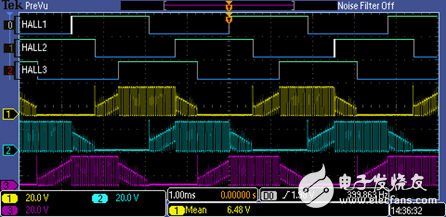
Figure 7: Three-phase Hall signal and winding back EMF waveform
6. Summary
This article describes how to develop a sensor BLDC motor control system on the PSoC4 platform, the newest member of the PSoC family introduced by Cypress. The design process of this paper shows that the rich resources of PSoC4 on-chip integration enable the commutation and Hall failure detection of BLDC motors to be completed by internal hardware, simplifying the software design of the control system and improving reliability. In addition, on-chip integrated op amps and comparators also place current sensing and protection inside the chip, making overcurrent detection faster and further reducing cost. As a result, users can use PSoC4 to design sensory BLDC motor control systems and products with superior performance and lower cost.
Wired Headphone including kids headphones /Music Headphones/Basic Wired Headphones/Studio Headphones
1. Frequency Range: 20Hz - 20KHz
2. Impedance: 32 Ohm
3. Sensitivity: 108dB+/-5dB(93db)
4. Speaker: 40MM
5. Plug Type: 3.5mm Stereo
6. Length of Cable: About 1.2m -1.5m
Materials: with rubbish finish and silk printing
Use for kids education/fashion show/pc /tablet
Wired Headphones,Wired Headphone With Mic,Kids Headphones For Ipad,In Ear Headphones
Shenzhen Greater Industry Co., Ltd. , https://www.szgreater.net