This section focuses on the implementation of a transposed FIR filter.
The unit impulse response h(n) of the FIR filter can be expressed as follows:
The FIR filter corresponding to the transposed structure, as shown in Fig. 1, has the same tap coefficient as the example of the direct type FIR filter explained in the previous section, and the filter order is 10.
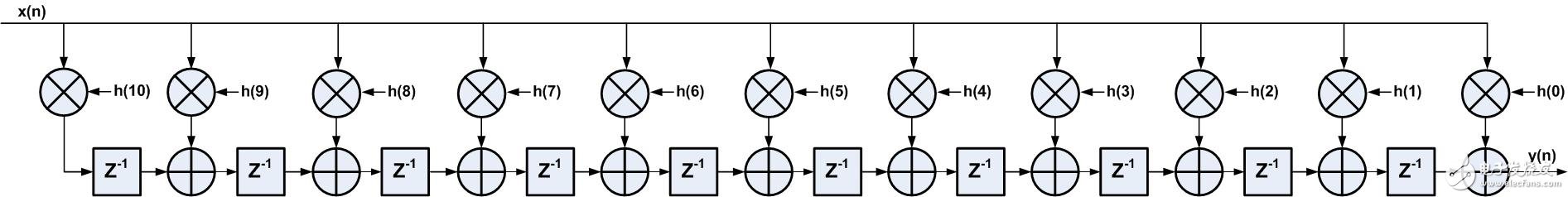
figure 1
It can be found that the transposed structure does not register the input data, but registers the result of multiply and accumulate, so that there is only one multiplication and one addition operation on the critical path, and the delay is shortened much compared to the direct type structure.
The combined results are as follows:
Number of Slice Registers: 1
Number of Slice LUTs: 18
Number of DSP48E1s: 11
Minimum period: 4.854ns{1} (Maximum frequency: 206.016MHz)
The critical path delay report is shown in Figure 2, where the multiply-accumulate operation delay Tdspdck_A_PREG_MULT 2.655ns; there is also a net delay actually has 1.231ns, so big because fanout=11, careful study can be found in h(n) expression In the formula, x(n) is multiplied with all 11 tap coefficients, so the fanout reaches 11, which is also a disadvantage of the transposed FIR filter: the fanout of the input data is too large.
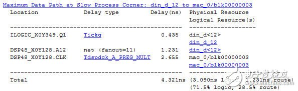
figure 2
Linear phase:
As with the direct type structure, the FIR filter of the transposed structure can also be optimized by the linear phase characteristic of the FIR filter. As shown in Fig. 3, the linear phase FIR filter transposed structure has a total of 11 tap coefficients, of which 5 pairs The coefficients are the same in pairs, so five multipliers can be omitted and six transposed FIR filters can be implemented with six DSP resources.
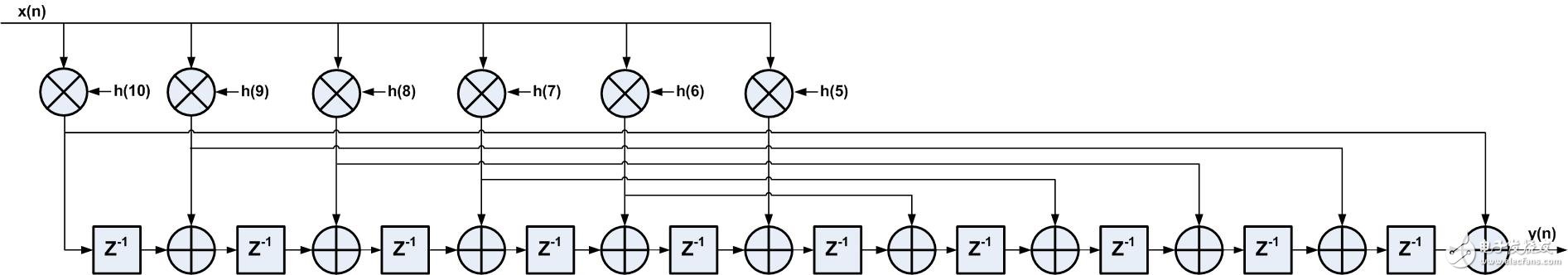
image 3
Pipeline implementation:
In order to further shorten the delay of the critical path, the multiplier and adder logic are separated, and the pipeline stage is added in the middle. As shown in FIG. 4, on the basis of the linear phase structure, a primary register is added, so that the timing is maximized. .
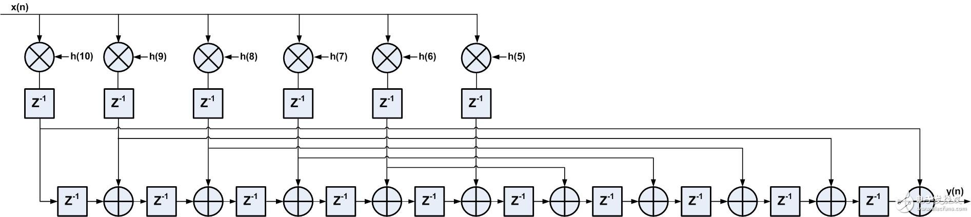
Figure 4
The combined results are as follows:
Number of Slice Registers: 355
Number of Slice LUTs: 340
Number of DSP48E1s: 6
Minimum period: 3.861ns{1} (Maximum frequency: 259.000MHz)
Figure 5 shows the delay report for the corresponding path in Figure 2 (Figure 2 is generated by ISE's TIming Analysis tool, Figure 5 is generated by PlanAhead's TIming Analysis tool), where the input signal is due to the linear phase structure The fanout is only 6, the delay is reduced from the original 1.231ns to 1.01ns; and after separating the multiplier and adder logic, there is only a multiplier delay on the critical path: 1.42ns.
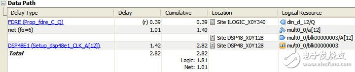
Figure 5
Win 3 Portable Dust Monitor is a robust monitor with wisdom software that makes dust monitoring easy:
Measures PM1, PM2.5, PM4 and PM10 Continuously
Data Logging and Downloading of Real-time and TWA Values for All Particle Sizes
Purpose designed for mines
Audible Alarm Greater than 85dB
Colour Coded Omni-directional Visual Alarm
Intuitive, user-friendly software
Ultra Wide Band Technology, can Receive Warning Messages from other devices, for example Gas Detector, which make the operation more safe and confortable.
Dust Monitor
Dust Monitor,Dust Detector,Dust Detection,Dust Measuring
ZHEJIANG HUACAI OPTIC-TECHNOLOGY CO LTD , https://www.win3safety.com