1 Overview
Liquid Crystal Display (LCD) is very suitable for embedded environment due to its size and power consumption. In recent years, with the improvement of microprocessor performance, the functions implemented by embedded systems are becoming more and more powerful, and the amount of data generated is also increasing. Correspondingly, the amount of data that needs to be displayed also increases. The use of LCD displays in embedded environments, due to limited conditions, is small and has limited display content. Moreover, the conventional LCD display mode always displays all the monitored information indiscriminately. When the amount of information monitored is very large, the information required by the user cannot be displayed in time. The multi-level menu display is a display mode for classifying and displaying information. The method selects and displays the display information according to the user's selection, so as to ensure that the user obtains the information required and ensures the real-time display of the information. Sex.
2 multi-level menu structure
The purpose of designing a multi-level menu is to classify the information that needs to be displayed, which is convenient for users to filter. Therefore, when designing the menu, it is necessary to set the number of levels of the menu and the number of submenus for each level according to the functions and requirements of the entire system. The topology of the entire multi-level menu is a tree structure, the main menu is the root node, the sub-menu is the branch node, and the last menu is the leaf node, as shown in Figure 1.
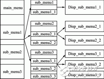
Figure 1 Structure diagram of the multi-level menu
3 multi-level menu programming
3.1 Cycle mode
The design idea of ​​the loop mode: predefine a structure containing 6 structural elements, 5 character types and 1 pointer type. The first character variable stores the index number of the current interface; the second character variable stores the index number that needs to be jumped when the "down" key is pressed; the third character variable is stored by pressing "up" The index number to jump to when the key is pressed; the fourth character variable stores the index number that needs to be jumped when the "enter" key is pressed; the fifth character variable is stored when the "esc (exit)" key is pressed. The index number that needs to be jumped; the sixth variable is the function pointer variable, which stores the entry address of the function to be executed under the current index number.
The execution functions and key index numbers corresponding to all the interfaces that need to be displayed are stored in the form of a structure. The specific implementation is as follows:
Typedef struct{
Uchardown_index;
Ucharup_index;
Ucharenter_index;
Ucharesc_index;
Void (*operate)();
}Key_index_struct;
Assuming the menu is divided into 3 levels and a total of 10 interfaces, there are:
Key_index_struct const Key_tab[10]={
{0, 0, 0, 1, 0, (*main_menu)},
{1, 2, 3, 4, 0, (*sub_menu1)},
{2, 3, 1, 5, 0, (*sub_menu2)},
{3, 1, 2, 7, 0, (*sub_menu3)},
{4, 4, 4, 4, 1, (*sub_menu1_1)},
{5, 6, 6, 5, 2,(*sub_menu2_1)},
{6, 5, 5, 5, 2,(*sub_menu2_2)},
{7, 8, 9, 7, 3,(*sub_menu3_1)},
{8, 9, 7, 8, 3,(*sub_menu3_2)},
{9, 7, 8, 9, 3,(*sub_menu3_3)},
};
Void Lcd_display(void){
Switch(Key_status){
Case enter:
Key_fun=Key_tab[Key_fun].enter_index;
Break;
Case down:
Key_fun=Key_tab[Key_fun].down_index;
Break;
Case up:
Key_fun=Key_tab[Key_fun].up_index;
Break;
Case esc:
Key_fun=Key_tab[Key_fun].esc_index;
Break;
Default:
Return;
Break;
}
Key_fun_Pt=Key_tab[Key_fun].operate;
(*Key_fun_Pt)();//Execute the operation of the current button
}
When the microprocessor scan keyboard detects that a button is pressed, according to the type of the button press, it returns the jump index number corresponding to the current interface, and executes the corresponding function.
Since the rendering of each interface is implemented by a separate function, it is found from the implementation of the loop mode that the entire screen needs to be redrawn every time a button press occurs. If the core processor is a low-speed main-frequency processor, it will flash when the interface is switched. Moreover, each interface has a fixed index number, which needs to be re-modified when adding or deleting interfaces, which reduces the portability of the program.
Xinxiang Mina Import & Export Co., Ltd. , https://www.mina-motor.cn