Generally speaking, in modern radio frequency systems, the frequency of the signal received by the antenna is very high and has a very small channel bandwidth. If you consider filtering out the required channel directly, the Q value of the filter will be very large, and the problems of gain, accuracy and stability of the high-frequency circuit, under the current technical conditions, the signal is directly demodulated in the high frequency band Is unrealistic. Using a mixer to down-convert high-frequency signals, channel filtering, amplification and demodulation at an intermediate frequency can solve the above difficulties encountered in high-frequency signal processing, but introduces another serious problem, namely, image frequency interference : When the frequency difference between the two signals and the LO signal is symmetrically located on both sides of the LO signal on the frequency axis, or their absolute values ​​are equal but the signs are opposite, then both signals are mixed after mixing Will be moved to the same IF frequency. If one of them is a useful signal and the other is a noise signal, then the frequency at which the noise signal is located is called the image frequency. This kind of interference phenomenon after mixing is usually called mirror frequency interference. In order to suppress the image frequency interference, the commonly used method is to use a filter to filter out the image frequency component. But because the filter works in the high-frequency band, its filtering effect depends on the distance between the mirror frequency and the signal frequency, or on the level of the intermediate frequency. If the IF frequency is high and the signal frequency is far away from the image frequency, the image frequency component is greatly suppressed; on the contrary, if the IF frequency is low, the signal frequency and the image frequency are not far apart, the filtering effect is poor. But on the other hand, because channel selection is performed in the intermediate frequency band, for the same reason, higher intermediate frequency frequencies have higher requirements for channel selection filters. Therefore, image frequency suppression and channel selection form a contradiction, and the selection of intermediate frequency becomes the key to balance the contradiction. In some demanding applications, two or three frequency conversions are often used to achieve a better compromise.
Generally speaking, a filter with a high Q value is required to filter out a narrow channel with a very high center frequency and a lot of interference. In the heterodyne structure, the signal frequency band is transformed to a much lower frequency, thereby reducing the requirement for channel selection filters. The heterodyne structure can be comprehensively considered from the aspects of image suppression and channel selection. Since the image signal reduces the sensitivity of the receiver, the choice of intermediate frequency requires a balance between sensitivity and selectivity. In terms of IEEE802.16e / WiMAX RF front-end design, the heterodyne transmitter has lower DAC requirements than direct conversion, and the mirroring problem becomes less prominent. However, the number of module devices has increased, which means more power consumption. The most common method of suppressing the image signal is to use an image suppression filter placed in front of the mixer. The filter is designed so that it has less loss in the useful frequency band and a large attenuation in the image frequency band. The heterodyne structure requires an image filter, but due to the large frequency separation, the design of the image filter is relatively simple. It should also be noted here that the accessibility and physical size of different frequency filters.
Superheterodyne receivers have great advantages in suppressing image frequency interference, sensitivity and selectivity, and there is no DC offset and signal leakage in multi-level conversion, but they also have high costs, high requirements for IR filters, and low needs. Noise amplifier (LNA) and mixer (Mixer) and 50W good matching and other shortcomings. In some cases, the image frequency suppression filter and channel selection filter are not suitable for monolithic integration, resulting in 50-ohm impedance matching of the front stage (such as LNA), which aggravates the gain, stability, power consumption, etc. of the LNA and other modules Performance tradeoffs.
The simplicity of the zero intermediate frequency (zero homodyne, direct down conversion) structure has two very important advantages over the heterodyne structure. First, the mirroring problem is overcome, so no mirror filter is needed, so the LNA does not need to drive a 50 ohm load. Secondly, the SAW filter and subsequent down-conversion stage can be replaced with a low-pass filter and baseband amplifier suitable for monolithic integration. However, the zero-IF structure is more difficult to suppress the interference outside the channel through the active low-pass filter during channel selection than the passive filter, and it generates DC offset, IQ mismatch, even-order distortion, flicker noise, and LO leakage. And other issues.
The zero-IF structure requires looser RF filters, and in the IF part, baseband filters are generally easier to implement than bandpass filters. In such a structure, MIMO technology is also easy to implement. In addition, in general, the zero-IF structure is also superior in power consumption. But it should be paid special attention to the problems of IQ equalization, high SNDR DAC design, DC offset cancellation, etc. Especially the DC offset cancellation at the receiving end, you need to be very careful and pay attention to the equalization of the channel, and The filtering of out-of-band noise requires a high-order filter. Welcome to reprint, this article comes from the electronic enthusiast network (http: //)
Compared with the zero-IF structure, digital processing can avoid the IQ mismatch problem. And the digital intermediate frequency structure also has many advantages. The IQ equalization problem and DC offset problem in the baseband-IF are easy to solve; the lower out-of-band shaping leakage requirements and adjustable amplitude; and the signal has lower requirements for the bandpass filter after the baseband-IF band, very It is easy to reach the index; the load capacity and amplitude requirements of the mixer do not have high requirements on the attenuator. However, digital intermediate frequency receivers have high requirements for analog-to-digital converters (ADCs). For example, ADCs need to have a sufficiently high dynamic range, low quantization noise and thermal noise, good linearity, and a large enough dynamic range. In some low-rate applications, such as IEEE802.15.4, band pass Σ-Δ ADC (Band pass Σ-Δ ADC) performance is more suitable, but band pass Σ-Δ ADC has a greater design difficulty. At the same time, it also means that the DSP performance of the baseband part is higher, such as window filtering. And DAC requirements have also increased accordingly, usually requiring 10 to 12 bits of resolution and higher rates. The performance of the image rejection filter has also become demanding, and the RF filter needs to be compensated even in certain frequency regions. Therefore, in WiMax applications, the digital IF structure has great potential, but it needs to weigh the design capabilities.
The comparison of the number of modules in the WiMax terminal transceiver system and its digital baseband processing part corresponding to the three receiving structures is shown in the following table. Some minor modules and some modules that are not in the transceiver channel are omitted here:
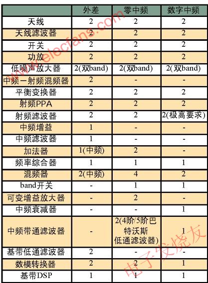
Table 1 Comparison of the number of end system modules of the three structures
Here, the blank bar does not completely mean that the module is not needed, but is determined according to specific design indicators. In addition, in comparing the performance difference of the error vector amplitude caused by the phase imbalance in QAM64 and QAM16 modulation, the digital IF structure has a slight advantage over the other two; in the QPSK modulation mode, the digital IF structure is only slightly when the gain imbalance is large Disadvantage. In general, under the three modulation modes of WiMax, the difference in the performance of the error vector amplitude caused by the phase imbalance in the three receiving structures is extremely small [1].
Table 2 gives the performance parameters of several WiMax chips. It can be seen that in these chips, the zero-IF structure is more common.
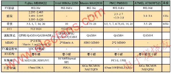
Table 2 Comparison of parameters of several WiMax chips
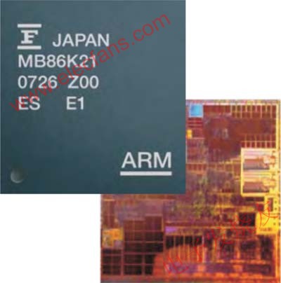
Figure 1 Fujitsu MB86K21 chip and layout
Figure 1 shows the Fujitsu MB86K21 chip and layout, and MB86K22 has made more improvements on this basis, so that it can work in more frequency bands, as shown in Table 2. Welcome to reprint, this article comes from the electronic enthusiast network (http: //)
The selection and design of the structure of IEEE802.16e / WiMax terminal chip and its chipset is a complicated process, and it is also another competition and design ability of the strength company in this respect. It is believed that with the development and application of IEEE802.16e / WiMax, more and better products will come out, and more and more will enter the life of ordinary users to meet the needs of the majority of users.
The Iphone 7 Plus Battery Case is also suit for iPhone 8 Plus mobile charging,It`s full cover&ergonomic light weight design protects your phone against everyday drop and tear,you will feel comfortable to use while charging your phone.We use the smart digital power management which enables our products to hold their charge for an extended period of time,making them more reliable than battery cases on the market.Charging will automatically stopped when battery full.This IPhone Battery Caseis with new charging head design for durable using and makes the connection more stable while charging your phone.


Iphone 7 Plus Battery Case,Iphone 7 Plus Smart Battery Case,Apple Iphone 7 Plus Battery Case,Best Iphone 7 Plus Battery Case
Shenzhen Hequanqingnuo Electronic Technology Co., Ltd. , https://www.hqqnbattery.com