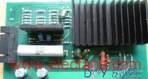
STK3048 is a pre-amplifier integrated circuit; STK6153 is a post-amplifier integrated circuit.
STK3048 is a 15-pin dual-channel single-row thick film package. Its exposed heat sink is connected to pin (8), but it is insulated from the internal circuit. (8) After the foot is grounded, it has a certain shielding effect on the internal circuit. There is no need to install a radiator when the thick film block is working.

There are two stages inside STK3048. The input stage has a differential amplifier with protection. The two diodes at the base of the differential tube protect. Its collector-capacitor series phase compensation network can prevent the input stage from generating transient distortion due to the burst signal. A set of mirror current sources is connected between the two collectors. The purpose of this circuit to connect people is to invert the current of the right input tube linearly and the left input tube to form two subtractive current sources, and implement current excitation to the subsequent stage. The main voltage amplifier stage is a common base common emitter circuit. The upper tube performs broadband amplification of the signal and provides impedance matching for the direct coupling between the input and output stages; the lower tube linearly outputs the amplified current of the upper tube to reduce the opening of the stage The ring is distorted and provides greater excitation power to the subsequent stage. The two-stage amplifier tube is supplemented by a constant current source as a load, which has strong suppression of power supply ripple.
STK6153 is a 10-pin mono channel single-row thick film package (two channels are required for two channels). The internal circuit has been electrically insulated from the exposed heat sink. STK6153 internally integrates constant voltage source bias, non-pre-stage push and non-stage composite current amplifier circuit. Adopting a fully complementary symmetrical structure, it has excellent characteristics such as high speed, high precision, high power and low noise. Due to the built-in bias of the constant voltage source, the unstaged high-power tube is always in the best working state and has excellent temperature compensation. The complementary output of the thick film block is designed as an inverted Darlington compound circuit, which outputs in the form of an open collector, which can reduce the output impedance.
The power amplifier circuit composed of STK3048 and STK6153 is shown in Figure 3-41 (the power supply and protection circuit are omitted). The internal circuits of the front and rear ICs are respectively analyzed in the dotted frame. The pre-stage small capacitors can use German-made WIMA or ERO high-quality capacitors, and the large electrolytic used for power supply filtering uses Nissan Marcon NIPPON, CHEMICON Nitsuko, Rubycon brand capacitors as the best. Each large electrolytic is connected in parallel with a WIMA 0.1uF ~ 0.33uF small Capacitor to improve frequency characteristics. The circuit can work normally without debugging. In terms of overall listening experience, the frequency bands in the full range are very balanced, with large dynamics, wide frequency response, low distortion, fast transient response, pure and powerful sound quality, and particularly low noise. Circuit sinusoidal power; 2X100W, distortion.

The internal circuit of STK3048 and STK6153 is relatively simple, and its sound quality is very good. However, the design of the peripheral circuit and the selection of peripheral components have a great influence on the sound quality of the IC, so this power amplifier uses the circuit shown in Figure 3-42. 
1. Use Gm to control the volume, connect the volume potentiometer to the gain control point of IC3 (NE5532), and change the depth of its negative feedback to change the volume. STK3048 works in the best stable state. There is almost no sliding noise when adjusting the volume. More importantly, the dynamic range remains the same when playing at a low volume, and the music details are vividly displayed at a large volume, without any sense of drag.
2. Adopt constant current negative feedback circuit, linear resistance R and R 'variable amplifier constant voltage mode is constant current mode to drive the load, so that the transient characteristics of the power amplifier can be improved, enhance the strength of bass and the clarity of treble.
3. Cancel the loop negative feedback capacitor, IC4 (NE5532) and peripheral components constitute the output midpoint zero servo circuit. Used to servo the â‘¡ and (14) pins of STK3048, the DC potential of the output of STK6153 will be drifted after the feedback capacitor is cancelled, and the high and low frequency resolution of the amplifier will be improved.
The amplifier's subjective listening evaluation: the treble is slender and clear, the midrange is bright and clear, the bass is full and strong, the sound range is clear, the harmonic distortion is small, the noise is low, and the dynamic range is extremely wide. Due to the large output power of this circuit, it should be noted that the power supply used must have sufficient capacity, and the STK6153 radiator should not be too small. The op amp IC is powered by an independent active servo power supply. In addition, the amplifier must be equipped with a speaker protection circuit.
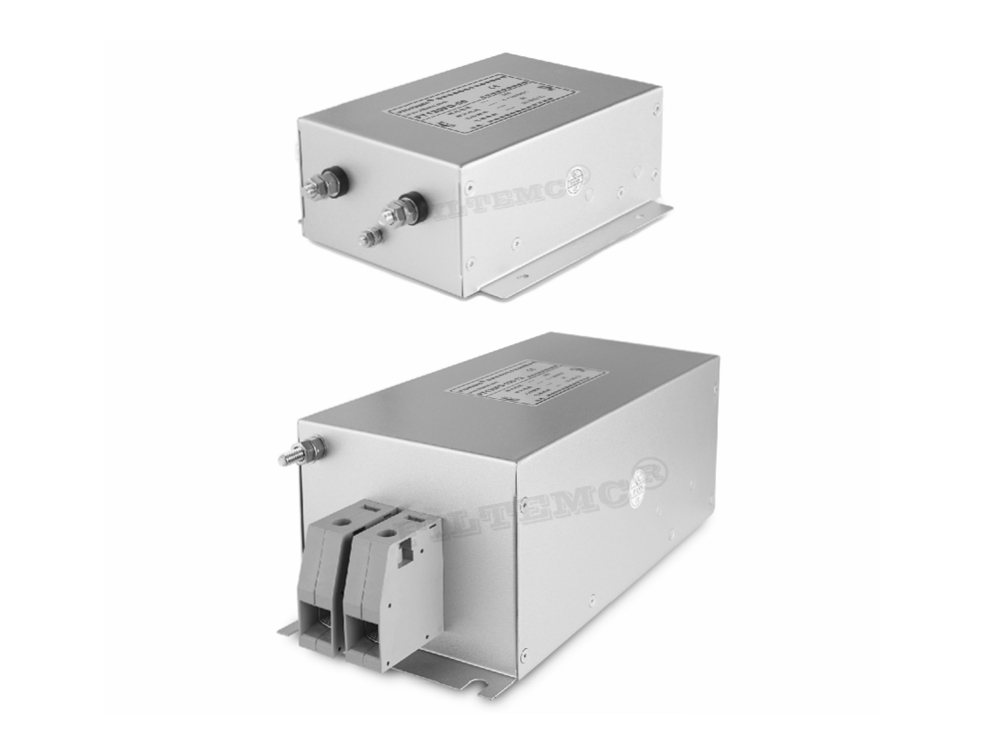
Features and benefits of PV inverter filters
Prevention of the electromagnetic interference of inverter towards controller and solar panel.
Prevention of the electromagnetic interference of inverter towards other grid-tied equipments.Effectively get rid of the electromagnetic pollution of inverter output current, guarantee the grid power quality.
Effectively eliminate the negative in uence of radiated interference of solar panel towards inverter and controller.
Greatly improve system reliability and effectiveness.
600VDC, 1200VDC or above high voltage versions available upon request.
Strict temperature rise control and much better performance than actually required assure productreliability even under special working conditions.
Brief introduction of PV Inverter Filter
Rated current: 1A~2000A
Stud or terminal block optional ( ≥ 250A it is copper bar)
Could be customized according to the real interference situation of customer's working field.

Passive Filter,PV Inverter Filter,EMI Filter For Inverter,Custom EMI Filters
Jinan Filtemc Electronic Equipment Co., Ltd. , https://www.chinaemifilter.com