Current detection in automotive applications includes controlling the current through the solenoid and injector. For example, in diesel injection, we use 48V or higher voltage to quickly increase the current of the induction injector to 20 amps. Once it reaches 20A, the current detection circuit will provide a feedback signal to the control circuit to keep the injector current at 20A unchanged. Current detection often enhances important performance or characteristics. Power window systems are a good example of the advantages of current detection technology. Since the torque of the motor is proportional to the current, the motor will stop working when the torque is too large. For example, if the human arm is stuck on the power window or the mechanical system fails, the motor will stop working. Current detection method
Current detection can be performed on the low or high voltage side of the load or power supply. The common mode voltage refers to the voltage on the shunt (not the differential voltage on the shunt), which is detected as zero volts on the low voltage side. Low-voltage side detection is the simplest, and the most basic amplifier circuit can be used. The difficulty of low-voltage side detection is that low-voltage side detection will affect the ground of the system, and may need to add more lines, and this method is usually not conducive to fault diagnosis. The high-side shunt amplifier in Figure 1 can detect very low differential voltages (typically 100mV or less) on very high power supply voltages, typically 13.8V in automotive applications. However, if it is an uncondited battery line, it will be affected by transients: if the battery direction is inadvertently misaligned, a condition of –13.5V will occur, and if a load dump or inductive kickback occurs, the maximum transient It can reach 72V. It is conceivable that the amplifier is usually powered by a single power supply of 5-12V (5V power supply is increasingly common), which requires the input pin of the amplifier to be connected to the common mode potential, which greatly exceeds the limit of the amplifier power rail.
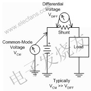 Figure 1 In the high-voltage side current detection, the common mode voltage is the main problem. The old-style shunt detection circuit is based on a differential amplifier, that is, an operational amplifier (operaTIon amplifier) ​​with four resistors around it to set the gain and provide a differential input. These resistors allow the op amp to accept common-mode voltages that exceed its power rails. However, this will also bring some of the following negative problems: First, the circuit must be configured as an attenuator to restore the gain in the subsequent operational amplifier stage, as shown in the IC structure diagram in Figure 2A, the gain of the operational amplifier will increase exponentially The amount of offset and drift of the first amplifier reduces overall performance. The second is to use a high common-mode voltage differential amplifier to increase the resistance network, so that it can still accept a higher common-mode voltage while still providing unity gain. The impact of a high common mode differential amplifier is that the noise gain of the operational amplifier is proportional to the common mode attenuation. The differential amplifier structure shown in Figure 2B uses an internal common mode attenuation of 20: 1, which makes the amplifier biased. The setting, drift and noise are 20 times larger than the operational amplifier itself. In addition, a larger input resistance will also cause higher noise.
 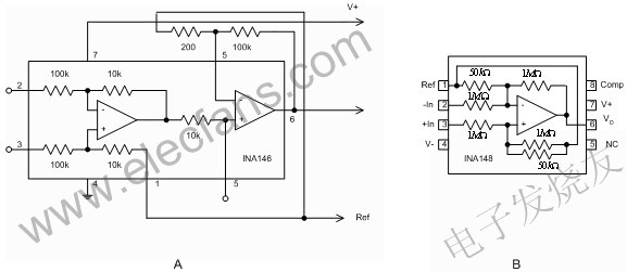 Figure 2 Resistive high common mode voltage differential amplifier current shunt monitor that can be used for on-board current detection is a high common mode voltage differential amplifier specifically used for shunt current detection, which can solve the limitations of the resistive differential amplifier. The main difference between current shunt monitors and differential amplifiers is that their common-mode voltage function usually only extends to positive voltages, while some current shunt monitors allow common-mode grounding. This will cause more derivative situations, which we will talk about later. The common mode voltage function also allows expansion to negative voltages. The current shunt monitor was designed to work with a single supply voltage from the beginning, usually with a minimum voltage of 2.7V. Figure 3 shows two types of current shunt monitor, divided into current output shunt monitor and voltage output shunt monitor. Current output shunt monitors usually have low quiescent current and require external output resistors, which allows the end user to set the gain. The voltage output device uses a fixed gain and does not require other components.
 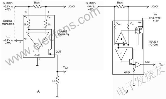 Figure 3 Two categories of current shunt monitors include: A) Current output shunt monitor and B) Voltage output shunt monitor General technical requirements for automotive applications
 On-board current detection is divided into two major types: one is directly connected to the battery, and the other is connected through a protection circuit that limits transient offset. The above conditions will affect the common mode voltage rating requirements on the current shunt monitor. The maximum voltage of the 12V electronic system in the vehicle is 14.4V, but the transient voltage on the battery bus device can reach up to 75V, and even battery pole switching may occur. We also need to consider another common mode situation: the shunt of the power line is turned on, and the ground is shorted. At this time, the common mode voltage is zero. It must be checked when the current flows, that is to say, the amplifier must also work properly at zero common mode voltage. Finally, let us consider the case of a pulse width modulation (PWM) solenoid driver as shown in Figure 4. In this example, the battery voltage is reached when the top of the solenoid is turned on. When the switch is closed, the voltage will return to the negative level of the diode voltage drop. This requires that the current shunt monitor can still operate at a common mode voltage as low as –2V.
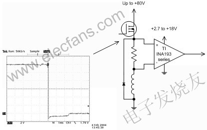 Figure 4 Current detection should be performed in PWM applications, even during the retrace period when the common-mode voltage drops to the negative voltage of the diode voltage drop. Current comparison
 In many applications, the current should be compared with a set value. Generally speaking, current shunt monitor, comparator and reference voltage are also needed for current comparison. In addition, the ideal comparator output should be well compatible with most common logic circuits. Figure 5 shows an example of current comparison. In this example, the current is compared to a simple single-voltage node using TI INA200 series current shunt monitors and comparators. R1 and R2 form a voltage divider to set the voltage node according to the built-in 0.6V voltage node of the INA200 series comparator. (The gain of the INA200 series is very characteristic: the gain of INA200 is 20, the gain of INA201 is 50, and the gain of INA202 is 100.)
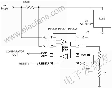 Figure 5: Simple single voltage junction current comparison. Some systems require more than one current limit level. For example, the system uses a lower current limit as an indicator of impending failure, and a higher limit as a sign to shut down the system. INA206-INA208 series current shunt monitors use two comparators to achieve the above functions. Some systems use delayed outputs for lower limits to avoid unnecessary triggering of transient offsets beyond the minimum limit. The circuit in Figure 6 feeds back the output of the INA206 current shunt monitor section to the two comparators, which generates an effective low output alarm and provides proper polarity for turning off the MOSFET buffer path. Figure 6 shows the circuit comparing the current with the two voltage nodes. The lower voltage node activates the alarm output, and we can configure an appropriate delay circuit for it to avoid false transient triggers. The lower voltage node has a built-in threshold of 0.6V at the input of the comparator. Q1 provides a buffer for the higher voltage node output, turns off the power through the power switch MOSFET, and enables Q2 if the current exceeds the upper limit. The higher voltage node uses the 1.2V reference voltage of INA206. INA206 has a latch function to avoid oscillation at a voltage node that does not have a latch function.
 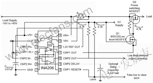 Figure 6 In this two-level current comparison circuit, the low-level delayed output can alert the imminent overload, and the upper limit of the latch function can turn off the load power supply.
China Electric Water Boiler Urn Suppliers
Here you can find the related products in Electric Water Boiler Urn , we are professional manufacturer of Electric Water Boiler Urn, Hot Water Urn ,Electric Hot Water Dispenser, Large Water Boiler ,Big Water Boiler with Reservoir and Taps,Commercial Electric Water Boiler Urn,We focused on international export product development, production and sales. We have improved quality control processes of Commercial Electric Water Boiler Urn to ensure each export qualified product.
If you want to know more about the products in Commercial Electric Water Boiler
Urn, please click the product details to view parameters, models, pictures,
prices and other information
about Electric Water Boiler Urn,portable hot water dispenser,hot water
dispenser for tea,hot water urn shabbat, tea boiler,Folding Travel Water
Kettle,folded silicon Water Bottle Mini Folding outdoor tea Kettle.
Whatever you are a group or individual, we will do our best to provide you with
accurate and comprehensive message about Commercial Electric Water Boiler Urn!
Commercial Electric Water Boiler Urn
Electric Water Boiler Urn,Hot Water Urn,Electric Hot Water Dispenser,Large Water Boiler,Big Water Boiler with Reservoir and Taps,Commercial Electric Water Boiler Urn
FOSHAN FORTUNE ELECTRICAL APPLIANCE CO.,LTD , https://www.coffelady.com