1. The video format is related to the clarity and authenticity of the signal
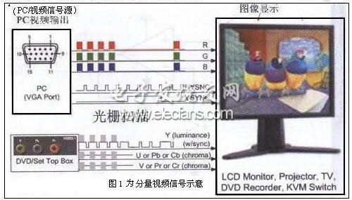
As we all know, the video transmission technology is very concerned about the clarity and authenticity of the video signal, as shown in Figure 1 for the common component video signal. Whether this can be done is inseparable from video signal filters, drivers, and multiplex switches and cable transmission devices. There are multiple input / output coupling and clamping combinations, including input AC or DC coupling, output AC DC coupling and various combinations of input clamps are the connection chips and technologies in the video transmission technology. It should be said that it is a video format. For this reason, the technical characteristics will be discussed and introduced.
2. The input technology of the interface in the video transmission technology
2.1 AC coupled video input method

When designing analog video circuits, analog video signals are generally input through AC coupling (as shown in Figure 2). This allows the receiving circuit to establish the optimal DC bias level, and the capacitor isolates the DC voltage of the drive signal on this side of the output device. The classic way of recovering DC in AC-coupled video signals is achieved by separating the entire synchronization part embedded in the video signal and establishing a digital pulse signal.
2.2 DC-coupled video input method (as shown in Figure 3 (a))

In order to adapt to those single-end input drivers whose reference voltage is ground level and DC coupling, as shown in Figure 3, filter / drive devices such as FMS641 7A, FMS6418B and FMS6419 are specially designed for DC input coupling. For example, the standard current mode output of the video / graphic display DAC. In order to make the current-excited general-purpose DAC produce an output voltage, this DAC circuit often uses a double-terminated 75Ω (AC impedance equivalent to 37.5Ω) resistor as the load. Therefore, this type of DAC output has a known ground-referenced DC level. Devices with this type of DAC circuit can be seamlessly connected to the video DAC output, and have the following advantages: no input coupling capacitor is required; there is no clamping settling time; there is no signal amplitude reduction due to input capacitor discharge; no generation Glitch pulse; there is no limitation of input impedance when using pulsed DC recovery loop; there is no need for on-chip synchronous separation, charge pump circuit and servo loop.
2.3 About input-level design in TV design
Figure 3 (b) shows an input stage circuit of a modern TV. The video signal is AC coupled to the DC recovery circuit, so the input video signal can have any DC offset. The input circuit is compatible with AC coupled and DC coupled video signal sources.
However, it should be pointed out that there has never been a universally adopted solution in the design of input stage in TV design. In the past, a large number of televisions used different input stages. Whether the signal came from an AC or DC coupled signal source, it may cause problems for some televisions. For so many different types of receiving equipment, to achieve universal compatibility is Impossible. Based on cost considerations, the low-end video signal source, which accounts for the vast majority of signal transmission equipment, uses DC-coupled output.
3. The output technology of the interface in the video transmission technology
3.1 AC coupled output and DC coupled output
Whether to AC-couple the output depends mainly on technical and cost factors. The AC-coupled output circuit includes a series capacitor (Figure 4a), while the DC-coupled output circuit does not have this capacitor (Figure 4b). Adding a capacitor to the output channel will result in cost Improvements, increased space, and video signal distortion will cause the output waveform to "tilt" upward or downward relative to the input waveform. Therefore, this field distortion is called "field tilt". The DC-coupled output has no field tilt, so designers of video output circuits must take it seriously.
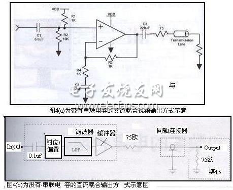
Since AC coupling has shortcomings, why is it still in use? There are two reasons. First, in order to play a protective role, the integrated circuit has not yet used a simple NPN emitter follower to drive the video output circuit before it is widely used. In case the output connector is shorted to ground or the power supply voltage, the capacitor prevents the NPN transistor from being damaged. The current integrated video amplifier has a solid short-circuit protection circuit, so it will not be damaged when a short circuit occurs. Second, starting from the technical characteristics, the most common method of outputting the video signal to the media display device is AC coupling (as shown in Figure 4 (c)), which allows the receiving circuit to establish a common mode level at its own input, This level is independent of the DC level of the input video signal. A 75Ω series resistor should be placed as close to the output as possible, which helps isolate the downstream parasitic interference generated from the output and provides the best signal conditions. The MAX4090 in Figure 4 (c) is the filter driver.
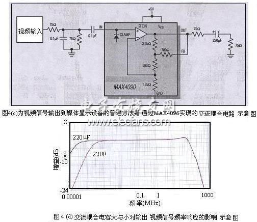
For AC coupling, one of the issues that should be paid attention to is that the coupling capacitance is usually relatively large, that is, 220 μF or greater. This is because the pole frequency formed by the capacitor and the 150Ω load (the sum of the reverse termination resistance and the input termination resistance) should be much lower than the frame frequency (25Hz or 30Hz). A 220μF capacitor forms a pole frequency of 5Hz, which is difficult to meet the performance requirements. Broadcasting equipment usually uses coupling capacitors of 470μF or 1000μF. Figure 4 (d) shows the high-pass response characteristics of AC-coupled output when using 220μF and 22μF capacitors. The minimum capacity of the AC coupling capacitor should be 200μF, which is the smallest coupling capacitor that can be used to obtain acceptable signal distortion.
Spice up your imaging landscape via seamless convex or concave curved video walls with angles, curves and just about any other creative design;A wide range of pitch options allows for high resolution video playback as well as creative architectural displays;Our fanless design allows for a no-noise LED Display solution that can fit in spaces of any size;Thanks to the light-weight design,up to 20 sq mts of soft LEDs can be packed inside one fligt case.So you get to save on both shipping and labor costs Indoor flexible LED displays are made of soft PCB and rubber material. It is extremely soft, can be made in any sizes and shapes for creative installations. it has a compact body design, 5mm thickness and magnetic connections . It can be fixed easily everywhere, including shopping malls, hotels, clubs halls, ect. Application Club and KTV entertainment arena.the television studio, personalized stage design, Club and KTV entertainment arena

Indoor Soft Led Display,Indoor Full Color Soft Led Display,Flexible Soft Led Display,Indoor Round Soft Led Display
Shenzhen Bako Vision Technology Co., Ltd. , http://www.rentalleddisplays.com