FlexRaY is a time-triggered communication bus, which requires high real-time performance. Therefore, relying on an embedded program composed of simple loops and interrupt service routines will not meet the requirements. At the same time, during the startup and operation of FlexRay communication, it is necessary to use the loop to query the bus status, which not only wastes a lot of system resources, but also easily causes program deadlock, which becomes a difficult problem in the application.
Based on the above problems, this article designs the communication part of the FlexRay bus in the wire steering based on the μC / OS-II operating system. On the basis of meeting the real-time requirements, the use of its multi-tasking feature saves system resources, avoids the occurrence of deadlock problems, and adds communication failure detection and alarm functions, which lays the foundation for the future development of wire-controlled steering systems.
1 FlexRay bus technology
In order to meet the needs of automotive wire control technology, the FlexRay Alliance released the FlexRay bus protocol in 2005. Its main features are: dual-channel transmission, the transmission rate of each channel is up to 10 Mb / s; it has a flexible use mode, supports multiple network topologies; high load rate; and provides a redundancy mechanism.
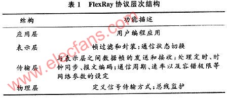
From the perspective of the open system interconnection reference model, the FlexRay communication protocol defines a four-layer structure: physical layer, transport layer, presentation layer and application layer. The functional description of each layer is shown in Table 1. In the presentation layer, the communication state switching controls the operation process of the entire FlexRay communication, and plays a very important role.
FlexRay protocol operation control (Proposal OperaTIon Control, POC) divides the communication state into several states, namely: configuration state (default configuration, configuration); ready state; wake-up state; startup state; normal state (normally active, normally passive) ; Suspended state. The state transition diagram is shown in Figure 1. When the controller host interface (Controller Host InteRFace, CHI) sends a command to the communication controller (CC), the CC enters the default configuration state from the suspended state, enters the configuration state after the configuration conditions are met, and completes the network initialization and node communication task initialization; You can enter the ready state and complete the internal communication settings of the node. If the communication ready conditions are not met, return to the configuration state to continue the configuration; in the ready state, the CC can send a wake-up frame to wake up the nodes that are not in communication in the network, and can also get the CPU started Communication command, complete synchronization with the FlexRay network clock; enter the normal state after successful startup, complete data transmission and reception; when an error occurs, can enter the suspended state from the normal state, and wait for the CHI command again.
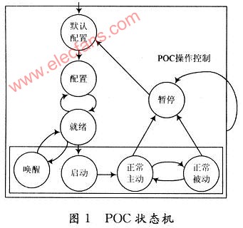
It can be seen that the controller needs to perform corresponding operations in accordance with the POC state, so there will be a loop detection of the POC state, which is easy to cause program deadlock and occupy a lot of system resources. According to the introduction of the operating system, its tasks exist in the form of a loop, so you can put the detected POC status into the task and execute it separately. Task scheduling through the operating system can avoid affecting the operation of programs in other tasks and improve the program Execution efficiency.
2 Based on MC9S12XF512 μC / OS-Ⅱ transplantation
μC / OS-Ⅱ is an operating system with open source code, which has the characteristics of high execution efficiency, small occupied space and excellent real-time performance. Using the task mechanism of the operating system, designing and implementing the Flex-Ray protocol can greatly improve the real-time and stability of the system, and can avoid the deadlock phenomenon when detecting the POC state.
At present, there are few MCUs supporting FlexRay communication on the market, and only Freescale's technology is relatively mature. Considering the cost issue, the 16-bit microcontroller MC9S12XF512 was selected as the system controller chip. The first problem to be solved when using the operating system is the migration problem. According to the file structure of μC / OS-Ⅱ, OS_CPU is needed when transplanting. H, (OS_CPU_A. ASM and OS_CPUC. C three files are modified to suit the needs of the MC9S12xF512 chip.
2.1 Modify OS_CPU. H file
OS_CPU. The H file defines the hardware information related to the CPU, including the storage length corresponding to various data types. For the stack in MC9S12xF512 is from the high address to the low address growth, so the constant OS_STK_GROWTH must be set to 1. At the same time, define the task scheduling function OS_TASK_SW () as the source of the soft interrupt.
2.2 Modify OS_CPU_A. ASM file
OS_CPU_A. The ASM file is to use assembly language to write the code related to the task scheduling part. Including the task-level task switching function OSCtxSw (), the interrupt-level task switching function OSIntCtxSw (), and the function OS-StartHighRdy () that allows the highest priority ready state task to start running.
MC9S12XF512 chip not only has FLASH page management register PPage, but also RAM page management register RPage, E2PROM page management register EPage and global register GPage. When the clock beat interrupt occurs, the chip will automatically push the CPU register onto the stack, but does not include the above registers, so in OS_CPU_A. In the three functions of the ASM file, you need to add statements to push and pop registers. Due to limited space, only take PPage code as an example:
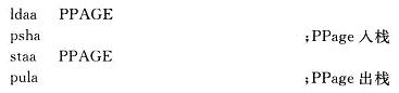
The stacking of registers must follow the order of GPage, EPage, RPage, PPage, and the opposite of stacking.
2.3 Modify OS_CPUC. C file
OS_CPUC. The C file is written in the C language related to the task scheduling part of the code, including the task stack initialization function OSTaskStklnit () and clock beat interrupt service subroutine OSTIcklSR ().
2.3.1 Modify the task stack initialization function 0STaskStkInit ()
Because μC / OS-Ⅱ uses the interrupt mode to implement task scheduling, it is necessary to use the function OSTaskStklnit () to simulate the stack structure after an interrupt occurs, reserve the storage space of each register according to the stacking order after the interrupt, and the interrupt returns The address points to the starting address of the task code. When writing, you need to write the code according to the order of stacking of X, Y, A, B, SP and other registers after the interruption of the chip. First set a breakpoint at the routine OSTaskStkInit () function, and then step through the program, and observe whether the X, Y, A, B, SP and other register states correspond to the stored values ​​written by the program. It is found that the address of the storage area corresponding to the SP value of the stack pointer is the storage address that is pushed into the stack when the interrupt is simulated, and the content of the pointer address of the task program is wrong, that is, it is not the pointer address of the task, so every time the task needs to be called All entered the wrong address to execute, and did not find the task code. By stepping through the OSTaskStkI-nit () function, you can find that the original program only stored the upper 8 bits of the PC pointer when storing the PC value of the task code pointer, but the last 8 bits were not saved, resulting in a pointer pointing error. So modify the program to:
*-wstk = (INTl6U) ((INT32U) task);
2.3.2 Modify the clock beat interrupt service subroutine OSTIckISR ()
The clock tick interrupt service subroutine OSTIckISR () is responsible for handling all timing-related tasks, such as task delays and waiting operations. In the clock interruption, the task in the waiting state will be queried to determine whether the delay is over, otherwise the task scheduling will be restarted. You can call OSIntEnter (). OS_SAVE_SP (), OSTimeTick () and OSIntExit () are implemented. The OSintEnter () function informs μC / OS-Ⅱ to enter the interrupt service subroutine. The OS_SAVE_SP () function is used to save the stack pointer. The OSTimeTick () function decrements the task delay counter for tasks requiring a delay of several clock ticks. When the program is repeatedly run When the counter is 0, it indicates that the task has entered the ready state, and the OSintExit () function marks the end of the clock tick interrupt service subroutine.
The most important point after that is to add the interrupt service subroutine OSTickISR () and the task-level task switching function OSCtxSw () to the corresponding position of the system interrupt vector table. The real-time clock interrupt module (RTI) is used here to generate the clock interrupt, so OSTickISR () should be connected to the vector table RTI position. The OSCtxSw () function uses soft interrupts to implement the task switching function, so the vector address of the soft interrupt service subroutine must point to OSCtxSw ().
After writing the above program, download the code to the hardware, and μC / OS-Ⅱ can be run on this system.
Ball Inflator Pump,Needle For Ball Pump,Air Pump For Balls,Pump For Basketball
SHENZHEN SMARTNEWO TECHNOLOGY CO,. LTD , https://www.newopump.com