Most high-fidelity speakers are composed of two or more speaker units. To restore high-quality audio signals in the entire frequency range of 20 Hz to 20 kHz, high-quality crossovers must be used. Since the speaker units of the respective speakers are different, the frequency divider cannot be simply substituted, and must be manufactured according to the characteristics of the specific speaker unit. Summarizing a set of more complete design, production and debugging methods, only requiring the producer to prepare a "Hugo Gold Disc" containing pure audio test signals of 20Hz ~ 20kHz, a microphone signal amplification circuit, a microphone and a digital Multimeter without the need for special test equipment.
For amateur speakers, it is recommended to choose the two-way frequency division method.
1. Selection of crossover frequency f The crossover frequency of two crossover speakers can be optimized between 2 and 5 kHz. Generally, the frequency f of the crossover point is selected within a range of one octave from the upper limit of the woofer unit and more than one octave from the lower limit.
Second, the frequency divider and the power distribution constitute the high and low units of the speaker, and their respective nominal powers are different, and in the actual program signal power spectrum, the proportion of high-frequency and low-frequency signals is also different, so After statistically averaging various signals, the analog signal power spectrum shown in FIG. 1 is obtained. By calculating the power spectrum of FIG. 1, the power distribution curve shown in FIG. 2 is obtained. When selecting the crossover point, we must consider the problem of power distribution, so that the tweeter has a certain margin. Figure 2 shows that the total power from 20Hz to 20kHz is normalized to 100%, and the power from 20Hz to a certain frequency f is the percentage of the total power. The application examples are as follows.
For example, in a two-frequency system with a crossover point of 2-5kHz, from the horizontal coordinate of 2-5kHz in Figure 2 to the intersection of the curves, the percentage is read from the vertical coordinate, then the power ratio from 20Hz to 2.5kHz is 87%, 2-5kHz The power ratio of ~ 20kHz is 13%. When the total power is 100W, the bass power Wlow = 100 × 87% = 87W, and the treble power Whigh = 100 × 13% = 13W.
When using the above power distribution relationship, please also pay attention to the power standard of the speaker unit. The general product label is the rated maximum sinusoidal power (RMS), and some manufacturers mark the peak power or music power for commercial purposes, but the value is generally 2 to 4 times the RMS power.
Third, the choice of frequency division method Although the frequency division method has 6dB / oct type, 18dB / oct type, 3dB landing point cross type and 12dB / oct type, 6dB landing point cross type, etc., but considering their advantages and disadvantages, It is recommended to use 12dB / oct type.
Fourth, the frequency division network design When the frequency division network, such as adding the load unit to the RC impedance compensation circuit, as a constant impedance design, this is of course the best. However, after reviewing a large number of books and periodicals, the author found that there are many calculation methods for the RC impedance compensation circuit, and the resulting RC value is also different, which makes it difficult for people to choose. They have to design by the frequency resistance method.
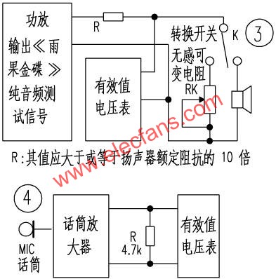
First, use the circuit shown in Figure 3 to measure the resistance of the high and low units at the crossover point (be careful not to use the nominal impedance of the unit, otherwise the error will be large, and then perform the calculations in the upper right table and click After connecting the LC components, the preliminary production is completed. The sensitivity of the high and low units is unbalanced and can be adjusted by resistance attenuation (a special article in the "Electronic News" No. 15 of 1997). It is recommended to use high-quality polypropylene capacitors during production to optimize Design hollow core inductors, fix the components on the printed board with hot melt adhesive, the inductors can be strengthened and fixed with cotton wire or plastic buckle straps, and connected by the method of ceiling welding to make separate high-end and low-end channels. the way.
5. Debugging method According to the inverse square law of sound pressure level, the point sound source is in free space, the distance is doubled, and the sound pressure level is attenuated by 6dB. Using this law, the following actual operations can be performed.
Install the speaker body and the speaker unit without connecting the frequency divider, use "Hugo Gold Disc" to test the signal, according to the normal playback mode, with a fixed volume of 2 ~ 3W, repeat the frequency f at the frequency division point, use the figure 4 A self-made simple sound pressure tester, test the sound pressure at 2m, adjust the volume of the microphone volume potentiometer to make the digital multimeter read, an integer that is easy to remember, write down and reserve. Then, connect to the low-pass network of the frequency divider, and place the sound pressure meter at 1m. The test reading should be the same as the last time, otherwise, increase (decrease) the capacitance according to the reading (smaller) until the reading is the same (this The frequency f at the time division frequency is attenuated by 6dB). Then, input the signal directly into the woofer again, adjust the test signal to an octave signal higher than the frequency f of the crossover point, test the sound pressure at 4m with a sound pressure meter, and record the reading for later use. Finally, connect to the low-pass network of the frequency divider, place the sound pressure meter at 1m, the reading is the same as last time, otherwise, adjust it slightly (at this time, the octave frequency f is attenuated by 12dB), so that the bass network is debugged. . The tweeter network repeats the above operation steps to adjust the inductance, and pay attention to the second step to input the octave signal lower than the crossover frequency f. In this way, a set of high-quality frequency divider is produced and debugged.
Die-Casting Products,Led Housing Die Casting,Aluminum Die Casting Product,Aluminum Die Casting Led
Yangzhou Huadong Can Illuminations Mould Manufactory Co., Ltd. , https://www.light-reflectors.com