1 Introduction
The forward operating voltage VF of the light emitting diode (LED) is the voltage drop produced by the LED between the two poles under the forward current IF. As an important parameter to characterize the electrical characteristics of LEDs, it is very important to obtain the forward voltage accurately and quickly to realize the detection of LED parameters, thereby improving the quality of LED device products and reducing production costs.
At present, there are many methods for detecting the forward voltage of the LED chip and the epitaxial wafer before packaging. The four-point probe method [1] is to contact the surface of the sample to be tested, inject a current into the sample to be tested and obtain the voltage-current relationship of the sample, and measure the electrical characteristics of the sample by establishing a mathematical model [2]; The contact is susceptible to damage to the wafer, which affects its circuit function. The superconducting quantum interferometer (SQUID) method realizes the detection of pn junction by observing and measuring the magnetic field distribution generated by photocurrent [3~5]; however, the detection system has high requirements for the detection environment, the instrument system is complicated, and the detection cost is high. . In [6], a method for estimating the forward voltage VF using junction temperature T, ideal factor n and photoluminescence (PL) spectrum is proposed, but the ideal factor value obtained by using the current-voltage characteristic to find the ideal factor method is significantly larger than Its true value [7], and the ideal factor n is not constant, but is reduced as the junction temperature increases [8].
In view of this, this paper proposes a non-contact method for detecting the forward voltage of LEDs using optical excitation and photodetection. This method is based on the connection between PL and electroluminescence (EL). Since the PL and EL of the LED are both carrier-injected and illuminating, the two are essentially identical, but the difference in junction temperature caused by the different injection modes causes the difference in the photoelectric characteristics of the two [9]. If the appropriate method is adopted to make the junction temperatures of the two injections close to each other, the PL spectrum can be used instead of the EL spectrum to detect the photoelectric characteristics of the LED chip [10]. In this paper, the short-time pulsed laser injection method is used to detect the forward voltage of the LED chip by non-contact of the luminescence spectrum. In this way, it is not necessary to directly detect parameters such as junction temperature and ideal factor, and only the spectrum can obtain a relatively accurate LED forward voltage value.
2 LED forward voltage and luminescence spectrum
Firstly, the relationship between the forward voltage VF and the junction temperature T is deduced. Secondly, the method of estimating the junction temperature by the LED luminescence spectrum is discussed. Finally, the junction temperature is used as a bridge to establish the relationship between the PL spectrum of the LED and the forward voltage.
According to the equivalent circuit model of the LED, when the light is injected and the external circuit is open, the forward current IF is equal to the photo-generated current Iph, and the forward voltage VF is equal to the open-circuit voltage Voc [6]. Therefore, the forward current IF is satisfied.
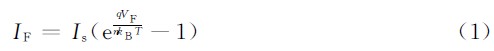
Where: IS stands for reverse saturation current; q stands for element charge; T stands for pn junction temperature; kB stands for Boltzmann constant; and n stands for ideal factor.
If the intensity of the light injection is changed, a total of N different injection intensities are measured, assuming that the forward currents of the i-1th and ith measurement points are IF(i-1) and IF(i), respectively, and the forward voltage VF(i-1) and VF(i), respectively
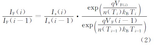
Where Ti-1 and Ti are the temperatures of the pn junctions at the i-1th and ith measurement points; n(Ti-1) and n(Ti) are ideal factors for the junction temperatures Ti-1 and Ti; (i-1) and Is(i) are reverse saturation currents at the i-1th and ith measurement points.
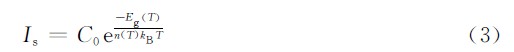
The relationship between the reverse saturation current Is and the forbidden band width Eg(T), the ideal factor n(T), and the junction temperature T is
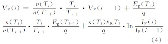
Substituting equation (3) into equation (2), the equations are taken logarithmically and simplified.
Literature [8] shows that the ratio of the forbidden band width of the LED to the ideal factor is approximately constant, ie
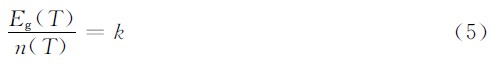
Where: n(T) and Eg(T) are the ideal factor and the forbidden band width when the junction temperature is TK, respectively; k is a constant. Since the photo-generated current Iph is proportional to the intensity of the injected light P, there is

Where Pi-1 and Pi are the light injection intensities of the i-1th and ith measurement points. Substituting equations (5) and (6) into equation (4), simplifying
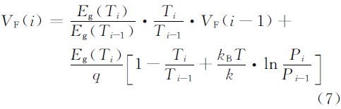
Equation (7) shows that the forward voltage VF of the LED can be recursed by using the forbidden band width Eg(T) of the LED chip and the corresponding pn junction temperature Ti under different light injection intensities. The forbidden band width Eg(T) is satisfied
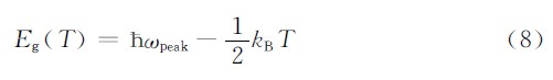
Where, the photon energy at the peak is ωpeak = hc/λpeak, where  is the Planck constant, c is the speed of light in vacuum, and λpeak is the peak wavelength of the luminescence spectrum. Equation (8) shows that the forbidden band width Eg(T) can be obtained from the peak wavelength of the spectrum. If the junction temperature Ti of the LED can be obtained from the luminescence spectrum, the forward voltage of the LED can be obtained.
The normalized linear function A(ω) of the LED luminescence spectrum is [11]
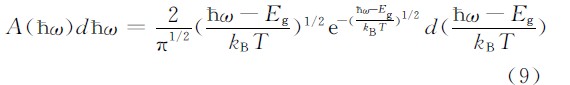
Where: ω represents the energy of the radiated photon; Eg represents the forbidden band width of the luminescent material; T represents the pn junction temperature of the device; kB represents the Boltzmann constant. Equation (9) shows that the observed normalized luminescence spectrum curve is mainly related to the forbidden band width Eg and the junction temperature T. In fact, for the case of direct transitions between bands, the forbidden band width Eg is also a function of the junction temperature T, which satisfies the Varshni equation [12],
Where: Eg(T) and Eg(0) are the forbidden band widths of LED luminescent materials at TK and 0K, respectively, in units of eV; α and β are Varshni temperature coefficients, which are constants related to materials. It can be seen from equations (9) and (10) that the shape of the LED luminescence spectrum is only affected by the junction temperature T, which theoretically establishes the relationship between the spectrum and the junction temperature.